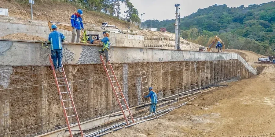
Dundee’s expansion along the Tay Estuary has driven deep basement and retaining wall projects in a challenging mix of glacial till, raised beach deposits, and estuarine silts. The city’s historic waterfront redevelopment, from the V&A to the new railway station, required excavation support systems that could hold back saturated ground while limiting lateral movement next to listed buildings. Diaphragm wall design in Dundee must account for high groundwater levels that fluctuate with the tide, stiff boulder clays that slow panel excavation, and the occasional sand lens that can cause sudden loss of slurry. Before specifying wall thickness or reinforcement, we always review the local geology through a detailed study of soil mechanics to confirm stratification and identify buried channels that might affect panel stability.
Panel stability in Dundee’s tidal ground requires slurry densities above 1.10 t/m³ and continuous monitoring of head loss against the estuary’s fluctuating water table.
Process overview
- Panel stability during fresh concrete placement (slurry density and head loss)
- Structural capacity of reinforced concrete panels under lateral earth and water pressure
- Serviceability limits for adjacent structures (typically 10-15 mm at basement level)
Local context
We worked on a five-storey basement near the waterfront where a sand lens at 8 m depth washed out during panel excavation, dropping the slurry level by 2 m in minutes. The adjacent road settled 40 mm before we could backfill and restart with a higher slurry head. That incident taught us to always run a full permeability profile and install relief wells before diaphragm wall construction in Dundee’s estuarine soils. Without that preparation, a single sand layer can turn a controlled excavation into a ground loss event that damages pavements, services, and building foundations. The cost of delaying the job for a week is far less than the liability for a settlement claim.
Reference standards
Eurocode 7 (BS EN 1997-1:2004) – Geotechnical design, BS EN 1538:2010 – Execution of diaphragm walls, CIRIA C760 – Guidance on diaphragm wall design and construction
Additional services
Feasibility Study & Ground Risk Review
Assessment of wall depth, panel layout, and groundwater control based on existing boreholes and trial pits.
Structural Design of Panels
Reinforced concrete panel design to Eurocode 2 and 7, including bending, shear, and crack control.
Slurry & Trench Stability Analysis
Calculation of slurry density, head loss, and trench stability factors for each panel.
Settlement & Third-Party Impact Assessment
Prediction of ground movements due to wall installation and excavation, with mitigation measures.
Typical parameters
Quick answers
What is the typical cost for diaphragm wall design in Dundee?
The design fee for a diaphragm wall in Dundee typically ranges from £1,320 to £5,460, depending on wall length, depth, and the complexity of ground conditions. This covers the structural analysis, stability checks, and construction drawings.
How deep can diaphragm walls be installed in Dundee's glacial till?
In the stiff boulder clay that underlies much of Dundee, diaphragm walls have been installed to depths of 35 m. The main limitation is the presence of sand lenses or gravel layers that can cause slurry loss; we always verify these with CPT soundings before finalising the design.
What groundwater control is needed during diaphragm wall construction near the Tay?
Groundwater in the estuarine deposits fluctuates with the tide, so we design the slurry head to exceed the maximum hydrostatic pressure by at least 1.5 m. In some areas, we also recommend installing deep wells or relief drains to lower the head before trenching.